NOTE 3—ISO 11092 Test Conditions—The environmental conditions
specified in the ISO standard are an air temperature of 35°C (isothermal),
a relative humidity of 40 %, and an air velocity of 1.0 m/s.
10.2 Procedures:
10.2.1 Feed water to the surface of the test plate and guard section.
10.2.2 Cover the test plate and guard section with a liquid barrier that prevents wetting of the fabric specimens by liquid water. Adhere the liquid barrier closely to the test plate and guard section with no wrinkles or air bubbles present.
10.2.3 Measure the bare plate evaporative resistance, (Rebp), in the same manner as that for Ret, except that the test plate and liquid barrier shall not be covered with a test specimen.
10.2.4 Measure the total evaporative resistance, (Ret), by placing a fabric or fabric system on the test plate. Place the test specimen on the test plate with the side normally facing the human body towards the test plate. In the case of multiple
layers, arrange the specimens on the plate as on the human body. Eliminate bubbles and wrinkles within the test specimen and air gaps between the specimen and the plate or between specimen layers by smoothing without compressing.
NOTE 4—In order to obtain consistent results, it is important that the sample remain flat against the plate. This will minimize the occurrence of unwanted air layers. Some fabrics and fabric systems have a tendency to ripple, swell, curl, or otherwise not lie flat during testing. The following protocol may be used in order to minimize the effect of this behavior.
1) Begin sweating hot plate test as normal, after approximately 20 minutes evaluate sample for flatness.
2) If necessary use the hand to eliminate bubbles, wrinkles, curls, etc., by smoothing the sample without compressing or stretching it. If tape or other device was used to secure the sample at the leading edge, remove prior to smoothing. After smoothing, re-secure the sample leading edge.
3) Place a metal bar, magnet, water vapor impermeable adhesive tape, or other retaining mechanism on each remaining edge of the sample. Care should be taken in the choice of the method to retain the sample. The retaining method should allow for possible additional movement of the sample during testing. Metal bars have shown to be suitable for this purpose. Appropriate metal bars are approximately 0.3-g per mm of length, 12-mm wide, 3-mm thick, and sufficient length to correspond with sample. Bars are to be replaced should they show signs of corrosion or wear.
4) Check the sample for smoothness and continue with testing. Should the sample not remain flat, repeat Steps 2-4.
10.2.5 After the fabric or fabric system reaches equilibrium conditions, record measurements for power input and the conditions given in
10.1 (with the exception of air velocity) every 1 min for a minimum test period of 30 min to determine the total evaporative resistance of the fabric plus the air layer,
(Ret).
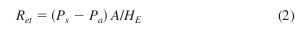
10.3 Calculations—Calculate the total resistance to evapo-rative heat transfer, (Ret), provided by the liquid barrier, fabric, and surface air layer using Eq 2.
|
where: |
|
|
|
Ret |
= |
resistance to evaporative heat transfer provided by |
|
|
|
the fabric system and air layer (kPa·m2/W) |
|
|
A |
= |
area of the plate test section (m2), |
|
|
Ps |
= |
water vapor pressure at the plate surface (kPa), |
|
|
Pa |
= |
the water vapor pressure in the air (kPa), and |
|
|
HE |
= |
power input (W). |
|
Ps and Pa are determined from water vapor saturation tables using Ts and Ta, respectively.
10.3.1 If the conditions of the test varied so that isothermal conditions were not maintained, or if non-isothermal condi-tions were used, then modify Eq 2 by subtracting Hc from HE (see Eq 5 in Part C).
10.3.2 Average the data from three specimens for the evaporative resistance tests to determine the mean Ret for the laboratory sample.
10.3.3 Determine the resistance to evaporative heat transfer provided by the specimen alone, Ref, by subtracting the evaporative resistance value measured for the air layer and liquid barrier, Rebp (that is, bare plate covered with the liquid barrier only), from the mean total evaporative resistance measured for the specimen, Ret.
NOTE 5—ISO 11092 defines the resistance to evaporative heat transfer provided by the fabric alone as Ret where “t” means “textile”. In this standard and others, “t” means “total”. The Ret values are also given in Pa units in ISO 11092. Therefore, for example, if the intrinsic thermal resistance of a fabric, Ref = 0.0132 kPa · m2/W in this standard, then it would be Ret = 13.2 Pa · m2/W in the ISO standard.
10.4 Calculate the permeability index for a fabric system including the surface air layer using Eq 3

|
where: |
|
|
|
im |
= |
permeability index (dimensionless), |
|
|
Rct |
= |
total insulation value determined in accordance with |
|
|
|
Part A, (K•m2/W), and |
|
|
Ret |
= |
total evaporative resistance determined in accordance |
|
|
|
with Part B, (kPa•m2/W). |
|
10.5 Calculate the permeability index for a fabric system alone using Eq 4
im = 0.060 Rcf/Ref
|
where: |
|
|
|
im |
= |
permeability index (dimensionless), |
|
|
Rcf |
= |
intrinsic insulation value determined in accordance |
|
|
|
with Part A, (K•m2/W), and |
|
|
Ref |
= |
intrinsic evaporative resistance determined in accor- |
|
|
|
dance with Part B, (kPa•m2/W).
|
|
11. Procedure Part C—Total Heat Loss in a Standard Environment
11.1 Test Conditions:
11.1.1 Temperature of the Test Plate, Guard Section and Bottom Plate—Maintain the temperature of these sections at 35 6 0.5°C without fluctuating more than 60.1°C during a test.
11.1.2 Air Temperature—Maintain the air flowing over the test plate at 25°C 6 0.5°C without fluctuating more than 60.1°C during a test.
11.1.3 Relative Humidity—Maintain the relative humidity of the air flowing over the plate at 65 6 4 % and without fluctuating more than 64 % during a test. The dew point temperature corresponding to 65 % RH at 25°C is 18°C.
11.1.4 Air Velocity—Adjust the air velocity to meet the calibration requirements. Maintain the same air velocity for all calibrations and tests, and without fluctuating more than 60.1 m/s over the duration of the test measurement.
11.2 Procedures:
11.2.1 Measure the bare plate thermal resistance, including the air layer and any apparatus contribution (Rcbp) in the same manner as that for Rct except that the test plate shall not be covered with a test specimen. The bare plate thermal resistance shall be an average of at least three measurements with nothing mounted on the test plate.
11.2.2 For thermal resistance measurements, calibrate the apparatus as follows:
11.2.2.1 Place one layer of calibration fabric on the test plate and measure the total thermal resistance (Rct), using Eq 1.
11.2.2.2 Place two layers of calibration fabric on the test plate and measure the total thermal resistance (Rct), using Eq 1.
11.2.2.3 Place three layers of calibration fabric on the test plate and measure the total thermal resistance (Rct), using Eq 1.
11.2.2.4 Place four layers of calibration fabric on the test plate and measure the total thermal resistance (
Rct), using Eq 1.
11.2.2.5 The apparatus shall meet the following constraints:
(a) A graph of total thermal resistance versus number of layers of calibration fabric shall be linear for the bare plate value, one, two, three and four layers.
(b) The slope of the linear regression shall be 0.0195 K·m2/W 6 10 %.
(c) No individual data measurement shall be outside 610 % of the value predicted by the linear regression.
(d) The intrinsic thermal resistance of four layers of calibration fabric shall be 0.078 K·m2/W 6 10 %.
11.2.2.6 If the apparatus cannot meet any one of these constraints, no specimens shall be tested until the apparatus is adjusted to meet these constraints.
11.2.2.7 Calibrate the apparatus, at least, whenever it is modified or repaired. Maintain the apparatus calibration in accordance with good laboratory practice.
11.2.3 Place the fabric or fabrics to be tested on the hot plate surface and measure the total thermal resistance (Rct). Place the test specimen on the test plate with the side normally facing the human body towards the test plate. In the case of multiple layers, arrange the specimens on the plate as on the human body. Eliminate bubbles and wrinkles within the test specimen and air gaps between the specimen and the plate or between specimen layers by smoothing without compressing. This smoothing of bubbles and wrinkles is one reason that the results from this test may not represent the performance of actual clothing worn by people. In many cases, trapped air in clothing can override any fabric effects.
11.2.3.1 Measurement of thermal resistance shall be done when equilibrium is reached.
11.2.3.2 Data used to calculate the thermal resistance shall be collected at least every 5 min.
11.2.3.3 Equilibrium shall be a rate of change of less than 3 % per hour of the calculated thermal resistance over a period not less than 30 min.
11.2.3.4 The coefficient of variation of calculated thermal resistance shall be less than 10 %.
11.2.4 After testing all specimens for thermal resistance, perform the following procedures before the evaporative mea-surements are made.
11.2.4.1 Feed water to the test plate so that water uniformly wets the test plate and guard section surface.
11.2.4.2 Cover the test plate and guard section with the liquid barrier to prevent wetting of the test specimen by the liquid water. Adhere the liquid barrier closely to the test plate and guard section with no wrinkles or air bubbles present.
11.2.4.3 Make no adjustments to the apparatus or test conditions. These parameters shall be the same for all the thermal and evaporative resistance measurements.
11.2.5 Measure the bare plate evaporative resistance, in-cluding the air layer, the liquid barrier, and any apparatus contribution (
Rebp) in the same manner as that for (
Ret) except that the test plate and liquid barrier shall not be covered with a test specimen. The bare plate evaporative resistance shall be an average of at least three measurements with only the liquid barrier mounted on the test plate. For this measurement, the local environmental climate shall be permitted to increase above 25°C, if necessary, to maintain test plate temperature at
35°C, or the plate temperature shall be permitted to decrease below 35°C, if necessary, due to limited energy available to the test plate.
11.2.6 For evaporative resistance measurements, calibrate the apparatus as follows:
11.2.6.1 Place one layer of calibration fabric on the test plate and measure the apparent total evaporative resistance
(RetA), using Eq 3.
11.2.6.2 Place two layers of calibration fabric on the test plate and measure the apparent total evaporative resistance
(RetA), using Eq 3.
11.2.6.3 Place three layers of calibration fabric on the test plate and measure the apparent total evaporative resistance
(RetA), using Eq 3.
11.2.6.4 Place four layers of calibration fabric on the test plate and measure the apparent total evaporative resistance
(RetA), using Eq 3.
11.2.6.5 The apparatus shall meet the following constraints:
(1) A graph of apparent total evaporative resistance (RetA) versus number of layers of calibration fabric shall be linear for the bare plate value, one, two, three and four layers.
(2) The slope of the linear regression shall be 0.0043 kPa·m2/W 6 10 %.
(3) No individual data measurement shall be outside 610 % of the value predicted by the linear regression.
(4) The apparent intrinsic evaporative resistance (RefA) of four layers of calibration fabric shall be 0.0172 kPa·m2/W 6 10 %.
11.2.6.6 If the apparatus cannot meet any one of these constraints, no specimens shall be tested until the apparatus is adjusted to meet these constraints.
11.2.7 Measure the apparent total evaporative resistance (RetA) by placing the fabric or fabrics to be tested on the hot plate surface. Place the test specimen on the test plate with the side normally facing the human body towards the test plate. In the case of multiple layers, arrange the specimens on the plate as on the human body. Eliminate bubbles and wrinkles within the test specimen and air gaps between the specimen and the plate or between specimen layers by smoothing without compressing. This smoothing of bubbles and wrinkles is one reason that the results from this test may not represent the performance of actual clothing worn by people. In many cases, trapped air in clothing can override any fabric effects.
NOTE 6— In order to obtain consistent results, it is important that the sample remain flat against the plate. This will minimize the occurrence of unwanted air layers. Some fabrics and fabric systems have a tendency to ripple, swell, curl, or otherwise not lie flat during testing. The following protocol may be used in order to minimize the effect of this behavior.
1) Begin sweating hot plate test as normal, after approximately 20 minutes evaluate sample for flatness.
2) If necessary use the hand to eliminate bubbles, wrinkles, curls, etc by smoothing the sample without compressing or stretching it. If tape or other device was used to secure the sample at the leading edge, remove prior to smoothing. After smoothing, re-secure the sample leading edge.
3) Place a metal bar, magnet, water vapor impermeable adhesive tape, or
other retaining mechanism on each remaining edge of the sample. Care should be taken in the choice of the method to retain the sample. The retaining method should allow for possible additional movement of the sample during testing. Metal bars have shown to be suitable for this purpose. Appropriate metal bars are approximately 0.3-g per mm of
length, 12-mm wide, 3-mm thick, and sufficient length to correspond with sample. Bars are to be replaced should they show signs of corrosion or wear.
4) Check the sample for smoothness and continue with testing. Should the sample not remain flat, repeat Steps 2-4.
11.2.7.1 Measure the apparent total evaporative resistance when equilibrium is reached.
11.2.7.2 Collect data used to calculate apparent total evapo-rative resistance at least every 5 min.
11.2.7.3 Equilibrium shall be a rate of change of less than 3 % per hour of the calculated apparent total evaporative resistance over a period not less than 30 min.
11.2.7.4 The coefficient of variation of calculated total evaporative resistance shall be less than 10 %.
11.2.7.5 If data collection cannot be completed within 4 h after placing the specimen on the test plate, remove the specimen from the test plate and allow to dry at least 24 h at 20 6 5°C, 65 6 5 % relative humidity before retesting. Subse-quent data reporting shall state that drying was required. If the retest of the specimen still cannot be completed within 4 h, report that the specimen cannot be tested by this procedure.
11.3 Calculations:
11.3.1 Calculate the total thermal resistance of the specimen using Eq
1.
11.3.2 Determine the average intrinsic thermal resistance of the sample alone (Rcf) by subtracting the average bare plate resistance (Rcbp) from the average total thermal resistance (Rct) of the specimens tested.
11.3.3 Calculate the apparent total evaporative resistance of the specimen using Eq 5.

|
where: |
|
|
|
|
RetA |
= |
apparent total evaporative resistance of the speci- |
|
|
|
men and surface air layer (kPa·m2/W), |
|
|
Ps |
= water vapor pressure at the test plate surface (kPa), |
|
Pa |
= |
water vapor pressure in the air flowing over the |
|
|
|
specimen (kPa), |
|
|
A |
= |
area of the test plate (m2), |
|
|
HT |
= |
power input (W), |
|
|
Ts |
= |
temperature at the test plate surface (°C), |
|
|
Ta |
= |
temperature in the air flowing over the specimen |
|
|
|
(°C), and |
|
|
Rct |
= total thermal resistance of the specimen and surface |
|
|
|
air layer (K·m2/W). |
|
11.3.4 Determine the average apparent intrinsic evaporative resistance of the sample alone (RefA) by subtracting the average bare plate evaporative resistance (Rebp) from the average apparent total evaporative resistance (RetA) of the specimens tested.
11.3.5 Determine the average intrinsic thermal resistance (
Rcf) of each specimen by averaging all values obtained over the equilibrium period (minimum of six). Determine the average intrinsic thermal resistance (
Rcf) of the laboratory sample by averaging the values for all specimens. If the results
for any of the three individual specimens vary more than 10 % from the average of all three, then repeat the test on the specimen(s) lying outside the 610 % limit. If the retest produces a value(s) within the 610 % limit, then use the new value(s) instead. If the retest remains outside the 610 % limit, then test an additional three specimens.
11.3.6 Determine the average apparent intrinsic evaporative resistance (RefA) of each specimen by averaging all values obtained over the equilibrium period (minimum of six). Deter-mine the average apparent intrinsic evaporative resistance (RefA) of the laboratory sample by averaging the values for all specimens. If the results for any of the three individual specimens vary more than 10 % from the average of all three, then repeat the test on the specimen(s) lying outside the 610 % limit. If the retest produces a value(s) within the 610 % limit, then use the new value(s) instead. If the retest remains outside the 610 % limit, then test an additional three specimens.
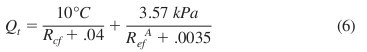
Calculate the total heat loss of the laboratory sam-pling unit using Eq 6.
|
where: |
= |
total heat loss (W/m2), |
|
|
Qt |
|
|
Rcf |
= |
average intrinsic thermal resistance of the labora- |
|
RefA |
|
tory sample determined in 10.3.5 (K·m2/W), and |
|
= average apparent intrinsic evaporative resistance of |
|
|
|
the laboratory sample determined in 11.3.6 |
|
|
|
(kPa·m2/W). |
|
12. Report
12.1 State that the specimens were tested as directed in Test Method F 1868, Part A, B, or C, as appropriate.
12.2 Report the weight, thickness, composition, and con-struction of the fabric tested, and the order and orientation of the specimen on the hot plate if a fabric system was tested.
12.3 Report any techniques used to restrain fabrics during
testing.
12.4 Report the results in accordance with Part A, B, or C, as appropriate.
12.5 Report any modification to the test.
12.6 Report the impingement angle, geometry, and velocity of the airflow.
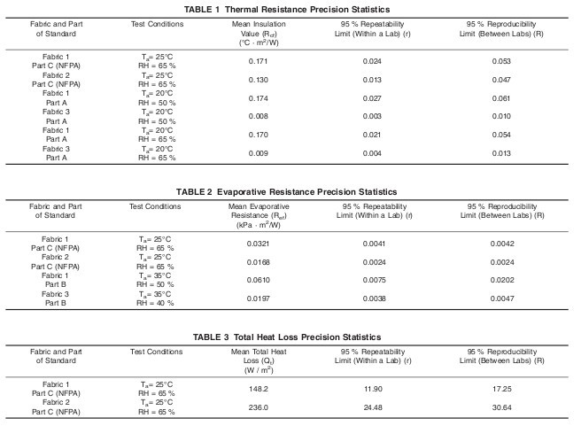
13. Precision and Bias 5
13.1
Interlaboratory Test Program—An interlaboratory
study of Parts A-E of this standard was conducted in 2001 in accordance with Practice
E 691. Samples of three fabric systems were tested in each of six laboratories under different environmental conditions. Three replications were conducted.
5 Supporting data have been filed at ASTM International Headquarters and may be obtained by requesting Research Report RR: F23–1005.
One lab’s data were omitted from the statistical analysis because they deviated significantly from the others.
13.2 The terms repeatability limit and reproducibility limit in
Tables 1-3 are used as specified in Practice
E 177. The tables
were calculated using the relationship: limit = 2.8 3 standard deviation.
13.3
Bias—Because there is no accepted reference material suitable for determining the bias for the procedure in this test method for measuring thermal and evaporative resistance, no statement on bias is being made.
14. Keywords
evaporative resistance; insulation; permeability index; thermal resistance; total heat loss
X1. END PRODUCT STANDARDS THAT REFERENCE THIS TEST METHOD
X1.1 Various end product standards for protective clothing refer to this test method. Among them are:
1) NFPA 1951, Standard on Protective Ensembles for Techni-cal Rescue Operations6
2) NFPA 1971, Standard on Protective Ensembles for Struc-
tural Fire Fighting and Proximity Fire Fighting6
3) NFPA 1977, Standard on Protective Clothing and Equip-ment for Wildland Fire Fighting6
4) NFPA 1994, Standard on Protective Ensembles for First Responders to CBRN Terrorism Incidents6
5) NFPA 1999, Standard on Protective Clothing for Emergency Medical Protective Operations6
6 Available from National Fire Protection Association (NFPA), 1 Batterymarch Park, Quincy, MA 02169-7471,
http://www.nfpa.org.
ASTM International takes no position respecting the validity of any patent rights asserted in connection with any item mentioned in this standard. Users of this standard are expressly advised that determination of the validity of any such patent rights, and the risk of infringement of such rights, are entirely their own responsibility.
This standard is subject to revision at any time by the responsible technical committee and must be reviewed every five years and if not revised, either reapproved or withdrawn. Your comments are invited either for revision of this standard or for additional standards and should be addressed to ASTM International Headquarters. Your comments will receive careful consideration at a meeting of the responsible technical committee, which you may attend. If you feel that your comments have not received a fair hearing you should make your views known to the ASTM Committee on Standards, at the address shown below.
This standard is copyrighted by ASTM International, 100 Barr Harbor Drive, PO Box C700, West Conshohocken, PA 19428-2959, United States. Individual reprints (single or multiple copies) of this standard may be obtained by contacting ASTM at the above address or at 610-832-9585 (phone), 610-832-9555 (fax), or service@astm.org (e-mail); or through the ASTM website (www.astm.org).